
The enigma machine was used in World War II to encrypt secret messages.
The Enigma machines are a series of electro-mechanical rotor cipher machines. The first machines were invented at the end of World War I by German engineer Arthur Scherbius and were mainly used to protect commercial, diplomatic and military communication. Enigma machines became more and more complex and were heavily used by the German army during World War II to encrypt radio signals.
The Enigma machine was used to both encrypt or decrypt Enigma messages (Enigma encryption is symmetric, which means that the same settings can be used to both encrypt or decrypt a message).
In this challenge we will create an enigma encoder program to encrypt and decrypt messages using specific Enigma settings. But before doing so we need to gain a better understanding of how the Enigma machine actually works. To do so you can use our online Enigma emulator to start encoding or decoding secret messages.

Inside the Enigma
The enigma machine is a fairly complex encryption machine which consists of four main sections:
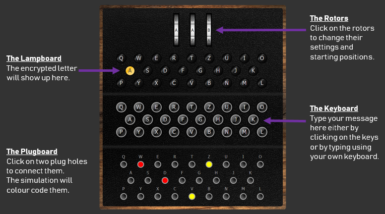
The Keyboard
The keyboard is used to retrieve the user input. The Enigma machine is a symmetric encryption machine. Which means that it can be used to both encrypt or decrypt a message using the same settings. The keyboard is hence used to either enter the plaintext that needs to be encrypted or the ciphertext that needs to be decrypted.
They keyboard consists of 26 keys for each letter of the alphabet. This means that encrypted messages will be joined up without any spaces or punctuation signs.
Notice how the keyboard starts with the letters QWERTZ instead of QWERTY. This is due to the fact that in the German language, the letter Z is more often used than the letter.
The plugboard
Once a key is pressed on the keyboard, it goes through the plugboard which provides the first stage of the encryption process. It is based on the principles of a substitution cipher, a form of transposition encryption.
To setup the keyboards, short wires are used to connect pairs of letters that will be permuted. For instance on the picture below the letter W will be replaced with a D and the letter D with a W as a (red) wire is used to connect these two letters/plugs. Similarly, letter V will become letter Z and Z will become V.
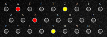
In a code book the plugboard settings would be recorded as follows: DW VZ
The Rotors
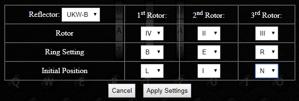
After the plugboard, the letter goes through the three rotors in order (from right to left), each of them changing it differently using a combination of transposition cipher and Caesar cipher! On the engima M3 there are three rotor slots and five rotors to choose from. Each rotor is identified using a Roman numeral from I to V. This provides a few settings of the Enigma machine: which rotors to use, and in which order to position them. In a code book this seeting would be recorded as IV II III (Left, Middle and Right rotors).
Each of the five rotors encrypt the letter differently using a transposition/permutation cipher and can be connected in the Enigma machine with a different Ring setting. Another setting is the initial position of the rotors: Which letters are you going to set each rotor to begin with (e.g. A/B/C../Z sometimes recorded in a codebook using numbers (01 for A, 02 for B up to 26 for Z). This creates a Caesar Shift (Caesar Cipher). On an Enigma machine, you can change the position of the rotors by turning the three wheels.
Different versions of Enigma (e.g. M4) included four rotors which made the encryption process and the number of possible settings even bigger.
On our Enigma M3 emulator, you can click on the rotors to access the Enigma rotors settings:

What makes the Enigma code particularly difficult to crack is that every time a key is pressed, the rotor on the right turns by 1 letter. Which means that the encryption settings constantly changes for each letter of a message. It also means that a single plaintext letter would be encrypted differently depending on its position in the message.
The rotors are also connected to each other so that when the rotor positioned on the right reach a specific letter, it triggers the rotor in the middle to rotate by one letter. Similarly when the rotor in the middle reaches a specific letter it triggers the rotor on the left to turn by one letter.
You will find more information on how the rotors operate on the following wikipedia page.
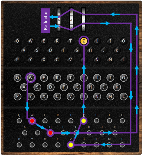
The Reflector
The reflector is another type of rotor inside the machine. Once the letter has gone through the three rotors from right to left, the reflector will reflect the electrical current back through the rotors, sending the encrypted letter through the rotors from left to right for another 3 stages of encryption and then through the plugboard again for a final substitution cipher. When going through the reflector, a permutation cipher is also applied to the letter.
Different versions of reflectors were used on different versions of Enigma machines. Each reflector would apply a different permutation cipher. Enigma M3 machines were equipped with either a UKW-B or UKW-C reflector. You can apply these two reflectors in the rotor settings window of our emulator (see screenshot above).
The lampboard
The lampboard is the final stage of the encryption process and is used to show the output (encrypted letter). It consists of 26 light bulbs, one for each letter of the alphabet.
The diagram below shows the journey of a letter through the encryption process of an Enigma M3.
Python Enigma Encoder
The Python program below allows you to encode and decode messages using the Enigma encryption.
You can apply your own Enigma settings by editing lines 3 to 9 of this code.

Solution...
The solution for this challenge is available to full members!
Find out how to become a member:
➤ Members' Area


